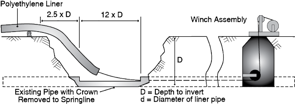
Typical Pipe Bursting Operation Layout
The first step in planning the pipe bursting operation is the optimization of the locations of the insertion and pulling shafts by using the insertion shafts to insert the new pipe into two directions. This optimization reduces the amount of excavation, mobilization, and demobilization efforts. These shafts should be planned at manholes or lateral connections in sewer lines and at fire hydrants or gate valves in water applications. The length of the run between the insertion and pulling shafts should not generate friction forces that exceed the capabilities of the bursting system and the tensile strength of the pipe. The next step is ensuring that the area around every shaft is sufficient for safe operation of the needed pieces of equipment and material staging. The insertion shaft has a flat section and sloped section; the flat portion must be sufficiently long to allow aligning the centerlines of the bursting head with that of the old pipe. The sloped section must be sufficiently long to allow the PE pipe to bend without any negative impact on the pipe (i.e., accommodate the bending radius requirements of the pipe). PE pipes can be cold bent to a radius of 25 to 30 times the OD of the pipe, depending on its SDR. Because of the pipe's ability to bend, the lay down area of the pipe prior to insertion does not necessarily have to be in line with the existing pipe. For example, for an 18" HDPE pipe with an SDR of 17, the minimum length of the insertion shaft is a horizontal length of 12 times the diameter of the new pipe (18 feet) plus a sloped length of 2.5 times the depth of the shaft as shown (Bennett and Ariaratnam 2005). The width of the pit depends on the pipe diameter and required working space around the pipe. The pulling pit must be large enough to allow for operation of the winch or pull-back device, along with removal of the bursting head.
Acceptable arrangements for traffic control, based on DOT and local government regulations, and for stretching the fused PE pipe with minimum inconvenience to nearby residents and businesses must be carefully considered. The flow bypass pumping and pipes layout should be also planned and considered. If dewatering needs arise, safe and proper flow discharge plans are required. The contractor submits the jobsite layout plan that reflects the intended method of construction and addresses the above mentioned considerations. The contractor does not start bursting before the engineer reviews and approves the jobsite layout plan, and the site inspector enforces the adherence to this plan unless there is a reason for the deviation approved by engineer or owner. If contaminated soil is excavated, the contractor should take the necessary measures to handle and dispose of this contaminated soil.